


Do you have questions about our features?
Would you like to learn more about our calculation functions, calculation outputs, or the Dendrit workflow? Then please contact us!


With our calculation tool for drinking water systems, you can ensure – as early as the planning phase – that high-quality drinking water is available throughout the building at all times. This is because water quality depends to a significant extent on the design of the drinking water system, the selection of pipe materials, the quality of workmanship, the sizing of the building’s piping system, and operational management.
The importance of planning that is fully compliant with regulations is evident from the fact that those responsible for a drinking water system must be prepared to provide proof of such compliance should drinking water hygiene issues be identified during operation. They must then be able to document that the planning, sizing, and construction of the entire drinking water system at the time of acceptance, as well as its subsequent operation, complied with generally accepted engineering standards (g.a.e.s.). This is a task you can easily master with our Dendrit CALHYDRA and Dendrit STUDIO solutions.
In addition, the calculation function allows you to determine the required pipe diameters for the supply and circulation lines of your drinking water systems by performing a pipe network calculation based on the technical regulations for drinking water systems.

Calculations using Dendrit give you peace of mind: Not only do they provide the sizing of all components in your drinking water system – in accordance with the g.a.e.s. – but they also deliver comprehensive documentation of the results in tabular form and as graphs. In addition, you receive analyses of the expected operating conditions in the piping system and at the draw-off points.
With Dendrit CALHYDRA and Dendrit STUDIO, you can calculate and visualize any cold- and hot-water pipe networks, either individually or in combination: with a branching structure for the vertical or horizontal distribution within a building, using either top-down or bottom-up distribution.
After completing your hydraulic calculation, you can highlight the corresponding flow path by clicking on a outlet fitting in the CAD drawing. You can view the associated result lists for the flow path and the sub-sections it contains, along with their characteristics, on an individual basis.
A diagram also shows the sum of the pressure components along the flow path, calculated for the end of each section. At each calculation point, these sums correspond to the minimum supply pressure (Bernoulli’s equation). At the end of the flow path, the flow pressure during peak flow must not exceed the minimum flow pressure at the withdrawal fitting—a static pressure of 5,000 hPa—for noise reduction purposes.
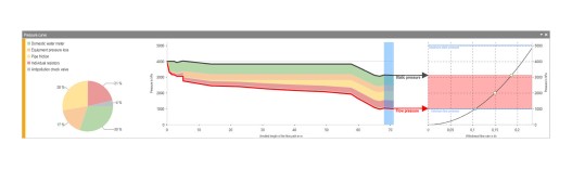
In conjunction with the discharge valve's performance curve, the graphical representation of the pressure profile allows you to quickly evaluate the calculation results.
To ensure that compliance with the hygiene and comfort requirements of DVGW Worksheet W 551 and VDI Guideline 6003 for tap fittings can be verified as early as the design phase, both the flow pressure and static pressure, as well as the possible flow rates at each tap fitting, are calculated. The operating range of the tap is clearly marked in color on the tap performance curve for your convenience.
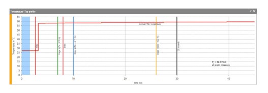
To prevent serious malfunctions, it is necessary to know – as early as the planning phase – the discharge time for the non-circulating water volume in the flow path for hot water outlets, and the discharge time for stagnant water with temperatures ≥ 25 °C for cold water outlets. With this information, you can calculate temperature draw-off profiles and verify compliance with the 30-second rule or comfort criteria.
Download a sample document for drinking water calculations here.
As you know, the hot water temperature in the storage tank and the piping system is particularly important for ensuring that drinking water meets hygiene requirements. By installing a suitable circulation system, you can ensure that the temperature in the distribution and riser pipes does not drop below 55 °C. Only floor-level or individual supply lines in residential buildings with a water volume of ≤ 3 liters may be installed without circulation.
In residential construction, hot water circulation typically involves only the distribution and riser pipes. Here, you can implement circulation systems of any configuration, with a circulation manifold located at the bottom or top, or with an in-line circulation system.
In healthcare facilities, you must also comply with the Robert Koch Institute’s “Guidelines for Hospital Hygiene and Infection Prevention” when planning, constructing, and operating drinking water systems. According to these guidelines, hot water should circulate through the floor-level pipes as close as possible to the point of use.
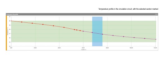
You can model and calculate hot water circulation to the draw-off points using conventional methods or in a material- and energy-efficient manner via hot water loop systems with flow dividers in vertical or horizontal pipe network structures. The heat losses of the pipes affected by the circulation are calculated for you in a differentiated manner, taking all influencing factors into account. You can vary the circulation flow rates by specifying a mixing factor within the limits specified by the standards.
To ensure that the calculated circulation flow rates can actually be achieved during operation, a control valve must be assigned to at least each connection of a circulation line to the hot water line, which requires the creation of additional pressure loss for what is known as hydraulic balancing. To ensure this state of hydraulic balance, the circulation system can be divided into several control levels and adjusted using a combination of static and thermostatic circulation control valves.
Key Benefits:
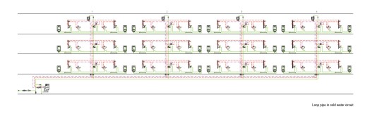
The Spöler-Cross method¹) is used for the detailed calculation of pressure losses in looped piping systems. This is a modified version of the Hardy Cross²) method for calculating looped piping systems and meshed networks, which additionally allows for the calculation of peak flow rates in the respective sections of a loop according to the rules of DIN 1988-300. Your benefit: This allows for the creation of larger looped pipe systems to supply multiple service units or in-line shower systems, etc. As a result, a looped pipe system is not limited to a single service unit—as specified by the standard. Looped pipe systems are always designed for a constant diameter to ensure that flow through the loop is as uniform as possible.
When loop lines are connected to flow dividers, this results in a significant water exchange during operation, accompanied by a drop in the temperature of the cold drinking water in the floor-level plumbing system.
1) Spöler, Thomas – Development of a Calculation Method for Sizing Interconnected Drinking Water Networks in Buildings, Taking into Account Simultaneous Water Withdrawal. Münster University of Applied Sciences, 2015 2) Cross, Hardy – x–Analysis of Flow in Networks of Conduits or Conductors, University of Illinois, Bulletin No. 286, 1936
A comparison of flow rate and temperature data from flow divider installations with comparable data from conventional distribution systems shows that water exchange is significantly more intensive here and is also distributed more evenly throughout the day. This more intensive and more even water exchange is due to the fact that water withdrawals at any point cause forced flow through all the ring lines upstream in the flow path (induction).
Compared to the current installation standard (in-line filter), the average daily water exchange rate for flow-divider installations is up to forty times higher. Of the stagnation phases that occurred during the observation period, more than 90 percent lasted less than 30 minutes. Good to know: No stagnation periods lasting longer than two hours were detected in the flow divider installations examined during the entire measurement period.
Compared to the current installation standard, the water changes, which are evenly distributed throughout the day, result in a significantly lower temperature level for the flow divider installations studied.
DVGW Water Information 90 defines a safe temperature for cold drinking water as below 20 °C. This is also in line with many international standards and has been virtually impossible to achieve with previous measures. To ensure hygienically safe cold water temperatures, Gebr. Kemper GmbH + Co. KG has therefore developed the KEMPER KHS CoolFlow cold water circulation system. The system is not only suitable for new construction but can also be retrofitted into existing buildings with minimal effort. With minimal structural work, the circulation manifold can be routed to the building’s entry point and the installation site of the cold water chiller. Optimal temperature control of the cold water, combined with a streamlined piping network, results in cost-effective and economical solutions. Circulating cold-water pipes are now insulated in the same manner as circulating hot-water pipes, in accordance with EnEV and ÖNORM standards, to keep heat gain as low as possible.
Recently, stagnation sections have been considered as a potential solution to prevent heat transfer from circulating hot-water pipes into in-wall installations. In this case, however, maintaining the temperature and ensuring water exchange must be achieved – at considerable cost – through draw-off valves or hygiene flushes. Since these flushing procedures cannot be performed without the user noticing, they are not suitable for hotels and healthcare facilities.
The “innovative” solution: cold water circulation with active temperature control. Therefore, in close collaboration with KEMPER, the calculation and simulation of cold water circulation networks using KEMPER KHS CoolFlow have been integrated into Dendrit CALHYDRA and Dendrit STUDIO. Use Dendrit CALHYDRA and Dendrit STUDIO to design, calculate, and analyze the system’s advantages, and use the physical simulation of the circulation technology to determine the temperature profile – and thus the actual operating conditions – as early as the planning phase.
The proven calculation and simulation methods for KEMPER’s innovative products enable you to verify, during the planning phase, that the temperature is maintained all the way to the point of use. By incorporating realistic ambient air temperatures into the calculation and simulation, planning reliability is significantly increased. Appropriate ambient air temperatures are suggested based on actual measured temperatures.
In Dendrit CALHYDRA and Dendrit STUDIO, cold-water circulation is modeled on a separate layer, just like the familiar hot-water circulation. The calculation results—such as power, flow rate, or pump pressure differential—are clearly displayed in Dendrit CALHYDRA and Dendrit STUDIO in the usual manner and can be documented accordingly.